项目分享| 如何让Arduino 和 Android之间实时传输图像
-
今天分享的项目是如何在Arduino 和 Android 手机之间通过蓝牙传输图像。有人会说这是不可能的,Arduino 速度太慢,无法快速处理大量数据。没错,但将所有“艰苦”的工作转移到其他设备,就可以实现了。

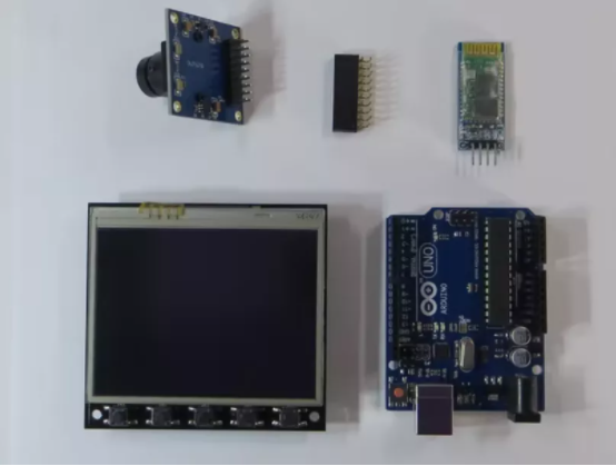
这个设备就是 Arduino 独特的 TFT屏扩展板,如果想了解更多这个TFT屏扩展板的信息和使用教程,参考文末的文章【1】【2】。在本教程中,演示了如何通过蓝牙连接 Arduino 和 Android 手机,从 Arduino UNO 上的 OV7670 摄像头获取照片并将其传输到 Android 手机。相反的,将图片(来自相机的图像)从 Android 手机传输到 Arduino UNO 并显示在TFT屏幕上。
先来介绍下这个TFT扩展板的特点:- 尺寸 3.5 英寸,分辨率 320x240,颜色数 65536(16 位)
- 电阻式触摸屏(XPT2046控制器)
- 5个按钮
- RTC IC DS1307配3V锂电池CR1220
- 用于连接 micro SD 卡的插槽
- 用于连接蓝牙模块 HC-05 (-06)、ESP8286 WiFi 模块的接口
- 用于相机 (OV7670) 的 20 针 (2.54 mm) 连接器
要完成Arduino 和 Android 手机之间通过蓝牙传输图像,除了TFT屏扩展板之外,还需要这些硬件:- Arduino UNO
- AC-DC 电源适配器 6-12 伏,>600mA
- 相机OV7670
- 蓝牙模块HC-06(HC-05)
- 安卓手机

这里注意:必须使用 6-12V电源适配器来给TFT屏扩展板供电,如果使用USB供电的话,500 mA 的最大电流不足以正常操作。
软件:- Arduino IDE
- TFT 屏库
- Android 手机的 APK 文件
Arduino 代码编写:所有的代码都是在 Arduino IDE 环境中编写,因此第一步就是在电脑安装 Arduino IDE - https://www.arduino.cc/en/main/software。然后,还需要为 TFT shield 安装一个库 - github.com/YATFT/YATFT (下载该库并解压到 Arduino IDE 目录下的“libraries”文件夹中即可)。
安装 Arduino IDE 后,为简单起见,可以先单独刷机,不带 TFT屏。步骤为:- 将 USB 线连接到 Arduino UNO 板;
- 在电脑上运行 Arduino IDE;
- 选择Arduino UNO所连接的对应端口;
- 下载ArduinoBluetoothCamera.ino(和文件ov7670_regs.h用于相机初始化);
- 单击按钮上传。
如果 Arduino UNO 板编程成功,您可以继续下一步。ArduinoBluetoothCamera.ino代码:
#include <YATFT.h>#include <util/yacam.h>#include <util/yacodec.h>#include <util/yasrl.h>#include "ov7670_regs.h"JPEG_DECODE jpeg_decode;YATFT tft(0);INTRFC ifc;CAM cam;CODEC codec;SRL srl;#define IMG_SizeX 320#define IMG_SizeY 240uint8_t mode = 0;uint8_t last_mode = 0;uint8_t start_capt = 0;uint16_t err;void setup(){// initialize the serial portSerial.begin(115200);// initialize the displaytft.begin();tft.SetColor(BRIGHTRED);tft.ClearDevice();}void loop(){// put your main code here, to run repeatedly:if (Serial.available()){uint8_t temp = Serial.read();switch (temp){case 0x10: // Send single Photomode = 1;start_capt = 1;if (last_mode != mode && last_mode != 2) {tft.begin();tft.SetRGB(); // Switch to RGB modecam.CamInit(&OV7670_QVGA[0][0]);cam.CamVideoPreview(0, 0, 1, true);codec.JPEGInit();codec.JPEGSetRegs(IMG_SizeX, IMG_SizeY);delay(1000);}break;case 0x20: // Continuous send Photomode = 2;start_capt = 2;if (last_mode != mode && last_mode != 1) {tft.begin();tft.SetRGB(); // Switch to RGB modecam.CamInit(&OV7670_QVGA[0][0]);cam.CamVideoPreview(0, 0, 1, true);codec.JPEGInit();codec.JPEGSetRegs(IMG_SizeX, IMG_SizeY);}break;case 0x30: // Receive single Photomode = 3;start_capt = 3;if (last_mode != mode && last_mode != 4) {tft.begin();tft.SetYUV(); // Switch to YUV mode}break;case 0x40: // Continuous receive Photomode = 4;start_capt = 4;if (last_mode != mode && last_mode != 3) {tft.begin();tft.SetYUV(); // Switch to YUV mode}break;default:break;}}if (mode == 1) // Send single Photo{if (start_capt == 1){start_capt = 0;last_mode = mode;mode = 0;CamCapture();}}else if (mode == 2) // Continuous send Photo{while (1){uint8_t temp = Serial.read();if (start_capt == 2){start_capt = 0;}if (temp == 0x21) // Stop ?{start_capt = 0;last_mode = mode;mode = 0;break;}if (CamCapture()) continue;}}else if (mode == 3) // Receive single Photo{if (start_capt == 3){//Start capturestart_capt = 0;last_mode = mode;mode = 0;Serial.print("!");srl.JPEGReadFromSerial(&jpeg_decode, // jpeg decode structure0, // x0 (left)0, // y0 (top)GetMaxX()+1, // x1 (right)GetMaxY()+1, // y1 (bottom)32000); // max image size}}else if (mode == 4) // Continuous receive Photo{uint8_t temp = Serial.read();while (1){if (start_capt == 4){//Start capturestart_capt = 0;}if (temp == 0x41) // Stop ?{start_capt = 0;last_mode = mode;mode = 0;break;}Serial.print("!");srl.JPEGReadFromSerial(&jpeg_decode, // jpeg decode structure0, // x0 (left)0, // y0 (top)GetMaxX()+1, // x1 (right)GetMaxY()+1, // y1 (bottom)32000); // max image size}}}uint8_t CamCapture(void){uint8_t temp = 0xff, temp_last = 0;bool is_header = false;uint32_t length = 0;length = codec.JPEGStart();uint32_t en_jpeg_address = ifc.rdReg32(0x414)<<2;int k = 0;if ((length >= 0x5FFFF) | (length == 0)){start_capt = 2;return 1;}temp = ifc.GetMem(en_jpeg_address+k);k++;length --;while ( length-- ){temp_last = temp;temp = ifc.GetMem(en_jpeg_address+k);k++;if (is_header == true){Serial.write(temp);}else if ((temp == 0xD8) & (temp_last == 0xFF)){is_header = true;Serial.write(temp_last);Serial.write(temp);}if ( (temp == 0xD9) && (temp_last == 0xFF) ) //If find the end ,break while,break;}is_header = false;return 0;}OV7670_regs.h:
#ifndef OV7670_REGS_H#define OV7670_REGS_Hconst uint8_t OV7670_VGA[][2] PROGMEM ={{ 1, 0x42}, // Size of byte, Address (ID){ 640/16, 480/16}, // Size X, Size Y{0b01000010, 0b00000100}, // Reset_Enable_N, 7|6|5|4|3|Vsync Invert|Hsync Invert|0{0x3a, 0x0C}, {0x40, 0xC0}, {0x12, 0x00}, {0x0c, 0x00},{0x3e, 0x00}, {0x70, 0x3A}, {0x71, 0x35}, {0x72, 0x11},{0x73, 0xF0}, {0xa2, 0x02}, {0x11, 0x80}, {0x7a, 0x18},{0x7b, 0x02}, {0x7c, 0x07}, {0x7d, 0x1F}, {0x7e, 0x49},{0x7f, 0x5A}, {0x80, 0x6A}, {0x81, 0x79}, {0x82, 0x87},{0x83, 0x94}, {0x84, 0x9F}, {0x85, 0xAF}, {0x86, 0xBB},{0x87, 0xCF}, {0x88, 0xEE}, {0x89, 0xEE}, {0x13, 0xE0},{0x00, 0x00}, {0x10, 0x00}, {0x0d, 0x00}, {0x24, 0x98},{0x25, 0x63}, {0x26, 0xD3}, {0x2a, 0x00}, {0x2b, 0x00},{0x2d, 0x00}, {0x13, 0xe5}, {0x13, 0xe7}, {0x1e, 0x30},{0x74, 0x60}, {0x01, 0x80}, {0x02, 0x80}, {0x15, 0x10},{0x4f, 0x40}, {0x50, 0x34}, {0x51, 0x0C}, {0x52, 0x17},{0x53, 0x29}, {0x54, 0x40}, {0x57, 0x80}, {0x58, 0x1e},{0x41, 0x10}, {0x75, 0x60}, {0x76, 0x50}, {0x77, 0x48},{0x3d, 0x92}, {0x3b, 0x00}, {0x04, 0x00}, {0xff, 0xff},};const uint8_t OV7670_QVGA[][2] PROGMEM ={{ 1, 0x42}, // Size of byte, Address (ID){ 320/16, 240/16}, // Size X, Size Y{0b01000010, 0b00000100}, // Reset_Enable_N, 7|6|5|4|3|Vsync Invert|Hsync Invert|0{0x3a, 0x0C}, {0x40, 0xC0}, {0x12, 0x10}, {0x0c, 0x00},{0x3e, 0x00}, {0x70, 0x3A}, {0x71, 0x35}, {0x72, 0x11},{0x73, 0xF0}, {0xa2, 0x02}, {0x11, 0x80}, {0x7a, 0x18},{0x7b, 0x02}, {0x7c, 0x07}, {0x7d, 0x1F}, {0x7e, 0x49},{0x7f, 0x5A}, {0x80, 0x6A}, {0x81, 0x79}, {0x82, 0x87},{0x83, 0x94}, {0x84, 0x9F}, {0x85, 0xAF}, {0x86, 0xBB},{0x87, 0xCF}, {0x88, 0xEE}, {0x89, 0xEE}, {0x13, 0xE0},{0x00, 0x00}, {0x10, 0x00}, {0x0d, 0x00}, {0x24, 0x98},{0x25, 0x63}, {0x26, 0xD3}, {0x2a, 0x00}, {0x2b, 0x00},{0x2d, 0x00}, {0x13, 0xe5}, {0x13, 0xe7}, {0x1e, 0x30},{0x74, 0x60}, {0x01, 0x80}, {0x02, 0x80}, {0x15, 0x10},{0x4f, 0x40}, {0x50, 0x34}, {0x51, 0x0C}, {0x52, 0x17},{0x53, 0x29}, {0x54, 0x40}, {0x57, 0x80}, {0x58, 0x1e},{0x41, 0x10}, {0x75, 0x60}, {0x76, 0x50}, {0x77, 0x48},{0x3d, 0x92}, {0x3b, 0x00}, {0x04, 0x00}, {0xff, 0xff},};#endif安卓APP程序
在 Android 手机上,您需要安装ArduinoTFT.apk,允许应用使用蓝牙和相机。
蓝牙模块需要在蓝牙模块中设置波特率为115200(命令“AT+UART=115200, 0, 0”)。这是 Arduino UNO 管理接收和处理数据的最佳速度。(理论上可以提高速度,优化数据接收和处理,但这需要更大的RAM)。
需要注意蓝牙模块连接到 Arduino UNO 的调试端口。因此,在使用蓝牙时,调试端口不可用。并且在对 Arduino UNO(配有蓝牙模块)进行编程之前,必须断开蓝牙模块。编程后,将其重新设置(!)
硬件组装非常简单:
- 将 Arduino UNO 和 TFT-shield 连接在一起;
- 将 OV7670 相机连接到屏蔽层 TFT-shield 上的 20 针连接器(有时我使用 2.54 毫米间距的有角度的 18-20 针连接器作为适配器);
- 将蓝牙模块HC-06(HC-05)连接到TFT-shield上带有“蓝牙”字样的4针连接器上;
- 将 6-12V 电源适配器连接到 Arduino UNO 板上的电源输入。

打开电源后,TFT shield 的屏幕应变为红色。这意味着愿意从 Android 手机接收命令。

在安卓手机上执行以下操作:
- 在 Android 手机上启动ArduinoTFT应用程序;
- 将手机置于水平位置;
- 开启蓝牙连接,选择检测到的蓝牙模块(HC-06);
屏幕上应出现两个窗口和四个按钮:
- 右上角窗口是手机的相机取景窗口;
- 左侧大窗口 - 接收或发送的图像。
按钮功能:- 将单个图像从 Android 手机传输到 Arduino;
- 将图像从 Android 手机连续传输到 Arduino;
- 将单个图像从 Arduino 传输到 Android 手机;
- 将图像从 Arduino 连续传输到 Android 手机。

图像大小为 320x240 像素 (2-5 kB)。项目不难,感兴趣的朋友可以试试。
文章【1】:https://create.arduino.cc/projecthub/alf81010/unique-tft-shield-for-arduino-uno-start-477f8c
文章【2】:https://create.arduino.cc/projecthub/alf81010/unique-arduino-tft-shield-ov7670-cam-live-view-7bf9bc
-


